Ball-on-Plate Balancing System
Development, implementation and Simulink simulation of a ball-on-plate balancing system using a 3RRS parallel manipulator and PID control.
This project explores the design, construction, and control of a ball-on-plate (BPS) balancing system. The system utilizes a 3RRS (Revolute-Revolute-Spherical) parallel manipulator as the platform, a resistive touch screen for ball position feedback, and a PID controller to achieve stable balancing and trajectory tracking. The project also includes a detailed Simulink model for simulation, analysis, and controller tuning.
System Overview
The ball-on-plate system is a classic control problem, known for its inherent instability and multivariable nature. This project aims to:
- Design and Build: Construct a functional BPS using a 3RRS parallel manipulator.
- Implement Control: Achieve stable ball balancing using a PID controller.
- Simulate the System: Develop a Simulink model to simulate the BPS dynamics for analysis and tuning.
- Trajectory Tracking: Implement software to enable the ball to trace predefined trajectories (circles, infinity symbols, squares).
This project demonstrates the application of control theory, mechatronics, and simulation techniques to a challenging real-world problem.
Hardware Components
The system consists of the following key hardware components:
- 3RRS Parallel Manipulator: Provides the platform for balancing the ball. This particular design offers good precision and control flexibility.
- Resistive Touchscreen: Senses the ball’s position on the plate. A cost-effective and readily available solution for position feedback.
- Stepper Motors (NEMA 17) with TMC2209 Drivers: Actuate the platform, precisely adjusting its tilt to maintain balance. The TMC2209 drivers provide smooth, quiet operation.
- Maker Uno Microcontroller (Arduino Compatible): Controls the system, reads sensor data, implements the PID algorithm, and drives the stepper motors.
- CNC Shield: Provides a convenient and organized interface for connecting the stepper motor drivers and other components to the microcontroller.
- Power Supply: Provides the necessary power for the stepper motors and microcontroller.
- 3D Printed Parts: Custom designed and 3D printed mechanical components for the platform and linkages.
Software and Control Algorithm
The software implementation includes:
- Arduino Firmware: The core control software written in C++ for the Maker Uno. It handles sensor input, PID calculations, inverse kinematics, and motor control.
- PID Controller: A Proportional-Integral-Derivative (PID) controller is used to stabilize the ball’s position. The controller calculates the necessary platform tilt based on the error between the ball’s actual and desired positions.
- Inverse Kinematics: A set of equations that translate the desired platform tilt (represented as a normal vector) into specific motor angles for the 3RRS manipulator.
- Touchscreen Input Handling: Reads the raw X and Y coordinates from the touch screen and converts them into meaningful position data. Includes scaling and offset correction.
Simulink Model
A detailed Simulink model was created to:
- Simulate BPS Dynamics: Model the ball’s motion on the plate using Lagrangian mechanics.
- Analyze System Behavior: Investigate the system’s response to different inputs and disturbances.
- Tune the PID Controller: Optimize the PID gains before implementing them on the physical system.
- Create a Digital Twin: To provide theoretical predictions about the system’s response

Results and Performance
The physical system was successfully assembled and balanced, achieving stable control of the ball.
Key Metrics:
- Stability: The system is able to maintain the ball within a reasonable area around the setpoint.
- Settling Time: The time it takes for the ball to settle near the setpoint after a disturbance was around 3.8 seconds.
- Steady-State Error:A slight steady-state error of approximately 25mm was observed primarily due to inherent biases of the system.
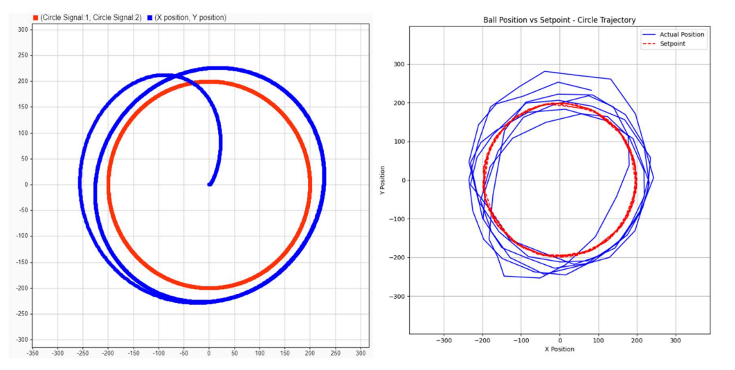
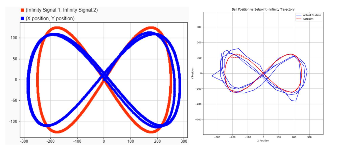
- Trajectory Tracking: The system was able to track predefined trajectories, including circles, infinity symbols, and squares
Circle Trajectory

Infinity Trajectory

Challenges and Future Work
- Reducing Steady-State Error: Addressing the steady-state error in the Y-axis through improved calibration and/or advanced control techniques.
- Mitigating Jitter: Implementing filtering techniques to reduce noise from the touch screen input and improve stability.
- Advanced Control Strategies: Exploring more advanced control algorithms like Model Predictive Control (MPC) or Fuzzy Logic Control (FLC) to achieve better performance.
- Hardware Optimization: Improving the mechanical design to reduce friction and backlash, and exploring higher-resolution sensors.
Conclusion
This project successfully demonstrates the design and implementation of a ball-on-plate balancing system using a 3RRS parallel manipulator. The system achieved stable balancing and trajectory tracking using a PID controller and a Simulink model for simulation and tuning. Further improvements in control algorithms and hardware design could lead to even better performance.